The Turret Joint
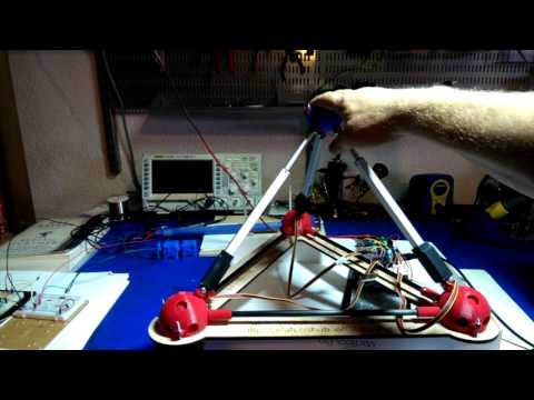
The keystone project of Public Invetion is The Gluss Project, an attempt to make massively scalable metamorphic spaceframe robots, or gluss. That project has successfully demonstrated the use of the Turret Joint, which are the brightly-colored, plastic, 3D printed joints in the video below:
Observe that as the actuators change their length, they change the angle between members coming into a joint, keeping all members pointed at the center of the joint at all times.
Motivation
In order to build a moving a spaceframe, a joint which brings multiple members together into a point is required. This may be called a “spherical” or “multi-member” joint. However, to use this in a robot it is necessary that the joint allow a certain amount of angular motion of all the members coming into the joint without significantly losing mechanical strength.
The Turret Joint accomplishes this by using a spherical shell trapped between two other spherical shells to support rotation which keeping the structural member always pointed exactly at the center of the joint. It thus must withstand tension and compression, but generates no torque or other unwanted off-axis forces. I call the joint the “Turret Joint” because it reminds me of the ball turrets used in science fiction spaceship combat carried on by laser turrets.
However, after constructing the first 3D printable Turret Joint, I learned that it was essentially invented in 1999 as expressed in this patent by Se-Kyong Song, Dong-Soo Kwon, Wan Soo Kim. This joint should really be called the “Song Kwon Kim” or SKK joint in honor of them. However, “turret-joint” better captures what it actually is shaped like, so I recommend we use that name, noting that it was invented by Song Kwon and Kim when mentioning it in writing. Their patent has now lapsed, and Public Invention does not seek patent monopoly on its work, so you are free to practice anything presented at this site. However, it would be illegal and unethical for you to attempt to patent anything found here.
More Views of the Design
Perhaps the easiest way to visualize the design is to use the “customizer” feature of our open-source published files at Thingiverse. Open my “thing” for the Turret Joint and click “Open in Customizer”. The Customizer allows you to create 3D-printed files directly for download and printing. However, it is not entirely up-to-date at the time of this writing.
But the joint must allow for motion. In particular, in a Gluss model, it must support the widest and narrowest angle which can be constructed by the individual Gluss members in the most fully and least fully extended configurations. (Click to see YouTube video on GlussBot #1.)
This repo holds the physical designs of such a joint, which I call a “turret joint”.
How it Works
You may wish to refer to the original Song, Kwon and Kim patent to understand how the joint works.

However, the following diagram is the way I think of it, and the means by which I computed the angle of allowed rotation, which is critical for proving that it will work with the gluss concept.
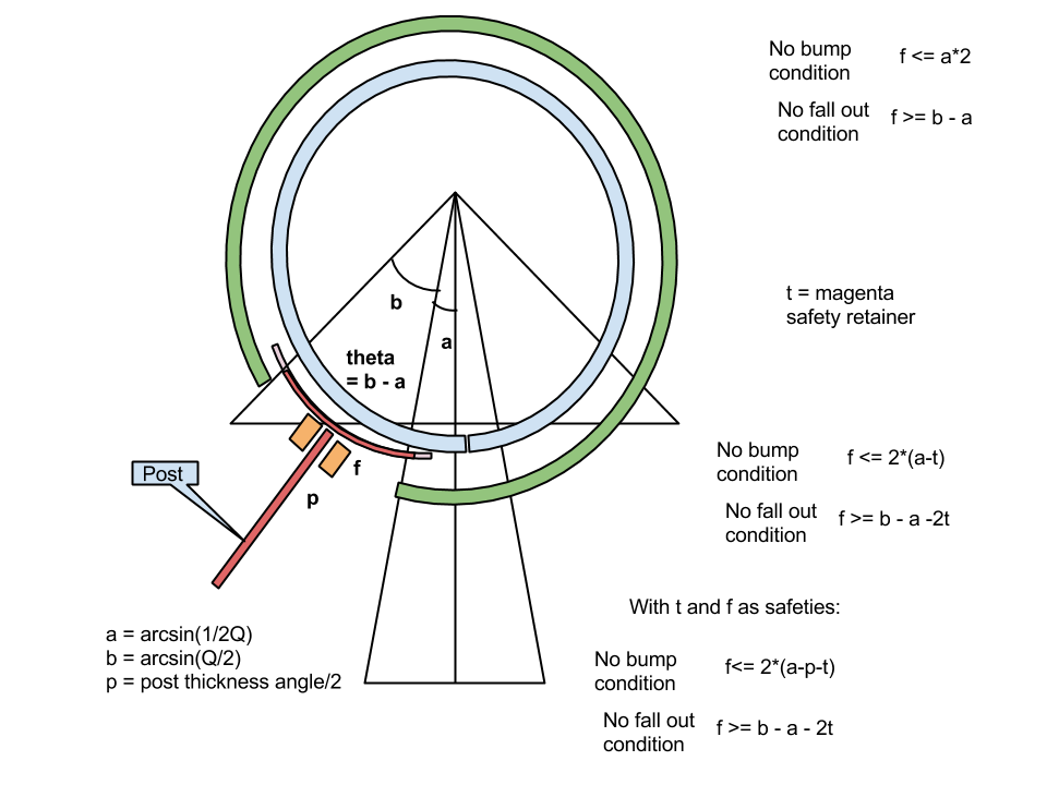
In the context of a a “gluss” robot, we seek a joint that supports the maximum flexibility of our actuators. We can describe any given actuator with a number, Q, which is the ratio of the fully extended linear actuator to the fully retracted linear actuator. In the case of the Firgelli L16 actuators that we actually use, the Q is about 1.5. Basically, the higher Q is the more eccentricity (acuteness) we have to be able to handle.

The basic condition is that the rotors must not bump into each other, and must not fall out of the hole. The larger the hole, the larger the rotor must be to remain captured. However, the larger the rotors are the sooner they “bump” if the angle becomes acute.
Using with the OctetTruss Pattern and the TetraHelix Pattern
The turret joint does not allow infinite rotation. Each member can move about 30 degrees. It is therefore incumbent upon us to partially match the geometry of the holes to the intended application.
Altough you may modify the OpenScad file that generates all of the parts to generate any custom geometry you need, it is useful to conisder the two most regular geometries that allow for scalability of static structures or dynamic robots.
These are the tetrahelix and the Octet Truss developed by Buckminster Fuller.


In the OpenSCAD file you will find parts to represent both of these geometries, which are slightly different. Note that the the tetrarhelix has chirality or “handedness”, because it can be constructed in either a left-handed helix or a right-handed helix. However, by putting extra holes in the part, I believe I have made it possible to create either with a single part (and the matching cap.)
Sharing and Patent Law
The Public Invention project does not seek patents on any of its inventions.
You are free to use anything you find in the repo under either the GPL or the Creative Commons Share-Alike license v4.0.
Public Invention seeks to give gifts to the whole world. If someone takes one of our freely published inventions and seeks a monopoly through a patent on it, it is directly counter to our mission, in addition to being fraudulent and illegal.
However, you are welcome to manufacture and sell a Turret Joint to your heart’s content, since the Song Kwon Kim patent has expired. Certain improvements made by Public Invention will not be patented. We (and the inventor in this case, Robert L. Read) would appreciate attribution of those improvements, after crediting Song, Kwon and Kim with the basic idea.
Research Problems
The Turret Joint presents a number of interesting research areas.
- Can we use more shells to increase the flexibility of motion? As an example, if we constructed a two-member strut, can we build one that allows 180 degrees of rotation? Or even 340 degress of rotation?
- We are currently using a triangular rotator for greater stability. However, we have not proven that this allows all motion possible. An interesting question, both mathematically and in terms of engineering, is: what is the best rotor shape?
- From a mechanical engineering point of view, we have expressed the argument that the joint is strong “because it has no off-axis forces”. This is a correct but vague argument, and far from a full analysis of the strength of the joint. If the joint were actually made of steel (or some other engineering-grade material), how much tensile and compressive force could it really withstand?
- The function of the joint depends upon it not binding. It the members must move overcome friction to align themselves. Prove that this is true and compute a level of friction at which they might fail.
This is project is a part of Public Invention (PubInv), a nascent organization that needs your energy and talent. Contact Us.
All materials produced by PubInv are free and open-source, and licensed either with the GPL (for code) or the Creative Commons Share Alike v 4.0 licenese (for text and designs.)

This file and all PubInv materials by Robert L. Read by default is licensed under a Creative Commons Attribution-ShareAlike 4.0 International License.